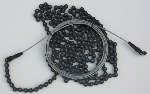
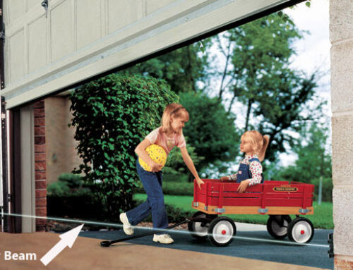
This chain-drive garage door opener DIY repair guide gives step-by-step instructions for replacing the chain and cable assembly. Located along the rail, the chain and cable assembly connects to the trolley and moves the trolley along the rail to raise and lower the garage door. If your garage door won’t move and the chain and cable assembly is damaged or broken, replace the assembly with a manufacturer-approved replacement part if it’s broken or damaged.
Parts Required
- Chain and cable assembly
Tools Required
- Step ladder
- Socket wrench set
- Phillips screwdriver
- Slot screwdriver
- General-purpose grease
- Work gloves
Before you begin make sure you wear work gloves to protect your hands. The following steps will guide you when replacing the chain and cable assembly on a chain drive garage door opener.
Step 1: Disconnect power
- Use a step ladder to access the garage door opener’s power cord and motor unit.
- Unplug the garage door opener.
Step 2: Take the garage door opener down
Tip: You may want to have a helper assist you when pulling the garage door opener down.
- Pull the emergency release rope to release the trolley from the garage door.
- Shut the garage door if it’s not already closed.
- Remove the fastener ring from the straight door arm connected to the outer trolley.
- Pull out the clevis pin while supporting the straight arm to disconnect the garage door from the outer trolley.
- Lower the straight and curved arms and rest them against the garage door.
- Open the light cover to access the wall control and safety sensor wires connected to the motor unit.
- Take a digital photo of the wall control and safety sensor wires connected to the motor unit. You’ll refer to the photo later when reconnecting the wires.
- Disconnect the wall control and safety sensor wires from the motor unit.
- Close the light cover.
- Remove the nuts, bolts and lock washers that secure the motor unit to the ceiling bracket.
- Support the motor unit with one hand as you remove the last bolt from the ceiling bracket.
- Carefully lower the motor unit down and rest it securely on top of the step ladder.
- Climb down the step ladder and lower the motor unit down to the garage floor.
- Move your step ladder by the garage door so you can remove the rail from the header bracket.
- Remove the fastener ring from the header bracket clevis pin.
- Pull the clevis pin out of the rail and header bracket while supporting the rail with one hand.
- Lower the rail to the garage floor.
Tip: To avoid scratching a decorative garage door, remove the nuts, bolts and washers from the curved arm and carefully rest the curved arm against the door when disconnecting the garage door from the outer trolley.
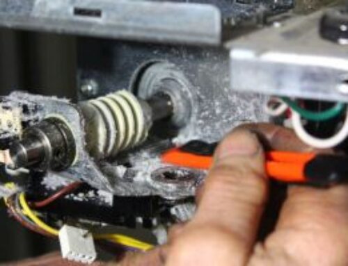
Step 3: Remove the chain and cable assembly
- Slide the outer trolley away from the inner trolley.
- Mark the rail to indicate the position of the inner trolley so that you can reinstall it in the same place after replacing the chain and cable assembly.
- Remove the outer nut from the trolley threaded shaft.
- Pull the threaded shaft out of the trolley.
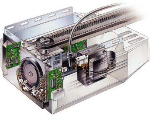
- Pull the chain off the motor unit sprocket.
- Pry off the master link clip-on spring from the master link cap on the trolley.
- Pull off the master link bar and master link cap.
- Remove the idler pulley nut and lock washer.
- Pull out the idler pulley bolt and slide the idler pulley out of the rail window.
- Pull the chain cable out of the rail window.
- Disconnect the trolley threaded shaft from the chain by removing the master link clip-on spring, master link cap and master link bar.
- Remove the chain and cable assembly.
Step 4: Install the new chain and cable assembly
- Lay the new chain and cable assembly beside the rail.
- Grasp the end of the chain cable and pass approximately 12 inches of cable through the rail window.
- Add general-purpose grease to the idler pulley center hole if it’s dry.
- Insert the idler pulley into the rail window behind the chain cable and line up the mounting hole.
- Reinstall the idler pulley bolt and tighten it firmly with the lock washer and nut.
- Make sure the idler pulley spins freely after tightening the nut.
- Connect the chain cable to the retaining slot by pushing the pins of the master link bar up through the cable link and trolley slot.
- Push the master link cap over the master link bar pins and past the pin notches.
- Slide the clip-on spring over the master link cap and onto the pin notches until both pins are securely locked in place.
- Position the inner trolley to the previously marked position on the rail.
- Align the rest of the chain and cable assembly along the rail, routing the cable onto the idler pulley and threading the chain through the chain spreader and around the motor sprocket, making sure not to twist the chain.
- Connect the trolley threaded shaft to the new chain by pushing the pins of the master link bar up through the threaded shaft mounting hole and the end link of the new chain.
- Push the master link cap over the master link bar pins and past the pin notches.
- Slide the clip-on spring over the master link cap and onto the pin notches until both pins securely lock in place.
- Thread the inner nut up to the top of the trolley threaded shaft and reinstall the inner lock washer on the threaded shaft.
- Making sure not to twist the chain, insert the trolley threaded shaft through the hole in the trolley. Using channel lock pliers, apply tension to the trolley.
- Insert the lock washer on the trolley threaded shaft and loosely thread the outer nut onto the threaded shaft.
Tip: Have a helper push the inner trolley toward the threaded trolley shaft to apply more tension to the chain and cable, making it easier to thread the outer nut onto the trolley shaft.
Step 5: Tighten the chain
- Tighten the outer nut to pull the trolley threaded shaft into the trolley, tightening the chain until the chain is about 1/4-inch above the base of the rail at its midpoint.
- Tighten the inner nut against the trolley to secure the adjustment.
Step 6: Reinstall the garage door opener
- Reconnect the rail end to the header bracket using the clevis pin and fastener ring.
- Position your step ladder under the motor unit ceiling bracket and carefully set the motor unit on top of the step ladder.
- Climb the step ladder and reinstall the motor unit to the ceiling bracket using the nuts, bolts and lock washers.
- Open the light cover to access the wall control and safety sensor terminals on the motor unit.
- Using your digital photo for reference, reconnect the wall control and safety sensor wires to the motor unit.
- Close the light cover.
- Reconnect the straight door arm to the outer trolley using the clevis pin and fastener ring.
- Re-engage the trolley.
Tip: Reconnect the curved door arm to the straight door arm using the bolts, lock washers and nut if you disconnected the curved arm from the straight arm when freeing the garage door from the outer trolley.
Step 7: Reconnect electrical power
- Plug in the garage door opener.
Step 8: Adjust the travel limits
- Run the garage door opener through a complete travel cycle to check upper and lower travel limits.
- If the garage door doesn’t close completely, adjust the down travel and cycle the door open and closed to test the adjustment. Continue to adjust the down travel until the door closes completely.
- If the door doesn’t open completely, adjust the up travel in the same manner.
Tip: Repeated operation of the garage door opener during travel limit adjustment may cause the motor to overheat and shut off. Wait 15 minutes to allow the motor to cool and then continue adjustments
Note: Before installing the new chain, it is important to mention the motor head has an open and close limit. The trolley on the rail has to match the open or closed position in the motor head. In order to make sure that the motor unit is in the closed position please do the following:
- Please stand behind the motor, facing the door and the rail should be in front of you; you may need to stand on a ladder so you can see the sprocket spin.
- Press the remote control, you want the sprocket to spin clockwise and stop. This is the closed position.
- Reposition the 2 pieces of trolley over by the door, the trolley assembly should be 8 to 10 inches from the end of the rail. The door should not be connected.
Warning:
Undertaking repairs or maintenance to appliances or power points can be hazardous. Should you choose to undertake repairs or maintenance you are assuming the risk of injury to you as a person and/or property. In an effort to reduce the risk, it’s advisable to use the proper tools and the safety equipment that are noted in the applicable guide. One must also make sure that they follow all the instructions. Do not proceed to any step until you are confident enough that you have clearly understood all the necessary steps that need to be followed in the repair or maintenance process. Some repairs and maintenance procedures should be performed by qualified technicians.
