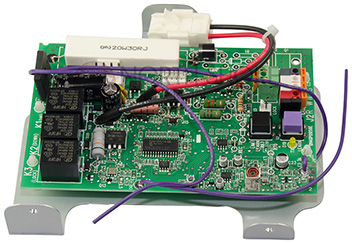
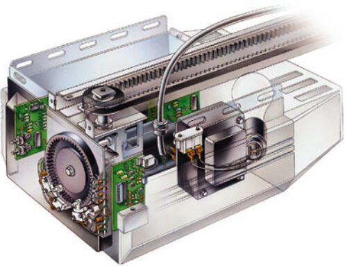
The logic board inside a garage door opener is the brains of the garage door opener. It contains the radio frequency (RF) receiver for the remotes and other control components. If the remote controls don’t work or the garage door doesn’t open and close properly, the logic board might have failed.
Logic boards are an internal board that controls all the functions of the garage door opener. They are found in most all electronic appliances. Manufactures are discontinuing their logic boards for older models more and more as time goes on. When logic boards burn out 90% of the time it is from electrical surges to the opener unit. These units are designed to always be plugged in and have constant power at all times. One big mistake homeowners make is plugging unit into an outlet that is always being turned on and off like a light switch or a power strip that is turned on and off only when needed. Or power outages can have the same effect.
Most manufacturers suggest that you plug your opener into a surge protector to eliminate this from happening. And you can get one at any grocery, drug or electronic retailer for about 10-15 dollars. Try to find a small surge protector about the size of the electrical outlet. Surge protectors that are a strip of plugs can be difficult to deal with for this application.
Tools Required
- Step ladder
- Work table
- Phillips screwdriver
- Nut driver set
- Wrench set
- Needle-nose pliers
- Work gloves
Follow the steps in this repair guide to replace it using a manufacturer-approved replacement part. Before you begin: Wear work gloves and safety glasses.
Step 1: Disconnect power
Use a step ladder to access the garage door opener’s power cord and motor unit.
Unplug the garage door opener.
Step 2: Take the garage door opener down
Tip: You may want to have a helper assist you when pulling the garage door opener down.
- Position a work table near the area under your motor unit to hold the garage door opener during the repair.
- Pull the emergency release rope to release the trolley from the garage door.
- Shut the garage door if it’s not already closed.
- Remove the fastener ring from the straight door arm connected to the outer trolley.
- Pull out the clevis pin while supporting the straight arm to disconnect the garage door from the outer trolley.
- Lower the straight and curved arms down and rest them against the garage door.
- Open the light cover to access the wall control and safety sensor wires connected to the motor unit.
- Take a digital photo of the wall control and safety sensor wires connected to the motor unit.
- You’ll refer to the photo later when reconnecting the wires.
- Disconnect the wall control and safety sensor wires from the motor unit.
- Close the light cover.
- Remove the nuts, bolts, and lock washers that secure the motor unit to the ceiling bracket.
- Support the motor unit with one hand as you remove the last bolt from the ceiling bracket.
- Carefully lower the motor unit down and rest it securely on top of the step ladder.
- Climb down the step ladder, lower the motor unit down and rest it on your work table.
- Move your step ladder by the garage door so you can remove the rail from the header bracket.
- Remove the fastener ring from the header bracket clevis pin.
- Pull the clevis pin out of the rail and header bracket while supporting the rail with one hand.
- Lower the rail and rest it on a rung of the step ladder so the rail is level with the motor unit on your work table.
Tip: To avoid scratching a decorative garage door, remove the nuts, bolts and washers from the curved arm and carefully rest the curved arm against the door when disconnecting the garage door from the outer trolley.
Step 3: Remove the logic board
- Remove the light cover and light bulb from the control panel.
- Remove the screws from the control panel and pull it out slightly to access the wire connections.
- Disconnect the wires from the logic board.
- Remove the logic board mounting screws.
- Pull the logic board off the control panel.
Step 4: Install the new logic board
- Thread the antenna wire through the control panel hole.
- Position the new logic board on the control panel.
- Install the mounting screws in the new logic board.
- Push the antenna wire through the hole on the corner of the control panel.
- Reinstall the control panel on the motor unit and secure it with the mounting screws.
- Reinstall the light bulb and light cover.
Step 5: Reinstall the garage door opener
- Reconnect the rail end to the header bracket using the clevis pin and fastener ring.
- Position your step ladder under the motor unit ceiling bracket and carefully set the motor unit on top of the step ladder.
- Climb the step ladder and reinstall the motor unit to the ceiling bracket using the nuts, bolts and lock washers.
- Open the light cover to access the wall control and safety sensor terminals on the motor unit.
- Using your digital photo for reference, reconnect the wall control and safety sensor wires to the motor unit.
- Close the light cover.
- Reconnect the straight door arm to the outer trolley using the clevis pin and fastener ring.
- Re-engage the trolley.
Tip: Reconnect the curved door arm to the straight door arm using the bolts, lock washers and nut if you disconnected the curved arm from the straight arm when freeing the garage door from the outer trolley.
Step 6: Reconnect electrical power
- Plug in the garage door opener.
Warning:
Undertaking repairs or maintenance to appliances or power points can be hazardous. Should you choose to undertake repairs or maintenance you are assuming the risk of injury to you as a person and/or property. In an effort to reduce the risk, it’s advisable to use the proper tools and the safety equipment that are noted in the applicable guide. One must also make sure that they follow all the instructions. Do not proceed to any step until you are confident enough that you have clearly understood all the necessary steps that need to be followed in the repair or maintenance process. Some repairs and maintenance procedures should be performed by qualified technicians.

